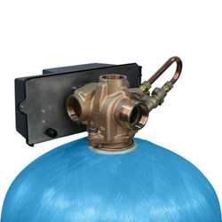
Fleck Valve 3150 Control Valve - Installation
Posted by Pure Aqua, Inc. on Sep 17th 2015
- Place the softener tank where you want to install the unit making sure the unit is level and on a firm base.
- During cold weather, the installer should warm the valve to room temperature before operating.
- All plumbing should be done in accordance with local plumbing codes. The pipe size for residential drain line should be a minimum of 1/2 inch (13 mm). Backwash flow rates in excess of 7 gpm (26.5 Lpm) or length in excess of 20 feet (6 m) require 3/4 inch (19 mm) drain line. Commercial drain lines should be the same size as the drain line flow control.
- Refer to the dimensional drawing for cutting height of the distributor tube. If there is no dimensional drawing, cut the distributor tube flush with the top of the tank.
- Lubricate the distributor o-ring seal and tank o-ring seal. Place the main control valve on tank. NOTE: Only use silicone lubricant.
- IMPORTANT: For valves equipped with electromechanical timers and stainless steel meters, refer to the Meter Dome and Union Orientation section.
- Solder joints near the drain must be done prior to connecting the Drain Line Flow Control fitting (DLFC). Leave at least 6 inch (15 cm) between the DLFC and solder joints when soldering pipes that are connected on the DLFC. Failure to do this could cause interior damage to the DLFC.
- Plumber tape is the only sealant to be used on the drain fitting. The drain from twin tank units may be run through a common line.
- Make sure that the floor is clean beneath the salt storage tank and that it is level.
 ENGLISH
 ESPAÑOL
 العربية
 PORTUGUÉS
 FRANÇAIS

